UGR table method
The UGR formula can be evaluated for realistic observing conditions and installation-specific exceptions, e.g. luminaire characteristics, luminaire arrangement, reflectance values of room boundary surfaces etc. Corresponding computer programmes are available.
The UGR limit values defined in EN 12464-1 for the various visual tasks must not be surpassed by the lighting installation in new condition and apply for installation values determined using the UGR table method.
The table method is also based on the UGR formula, however with standardised basic parameters. These basic parameters are:
Standardised observer conditions: The sitting (standing) observer is observing the luminaire arrangement from the room’s wall at an eye level of 1,2 m (1,7 m) above the ground (fig.).
Standardised room sizes x and y specified as a multiple of the "luminaire height H above the observer’s eye".
Standardised luminaire arrangements: The luminaires are arranged on the ceiling longitudinally or crosswise at regular distances (fig.).
Standardised reflectance values for ceiling, walls and floor.
Photometric characteristics (average luminance of the light-emitting surface) of the luminaires in question.
UGR tables are provided by the luminaire manufacturer. The planner rates the lighting installation to be assessed according to these standard specifications and gathers the UGR value for the observer’s viewing direction "parallel to the luminaires" or "across the luminaires" from the tables; see also example in section "Application of UGR tables" on the following pages. In most cases it is sufficient to determine the UGR value for the main viewing direction.
All assumptions made in the determination of the UGR value must be specified in the planning documentation. The change in UGR values for different observer positions within a room can be determined using the formula (or an extended UGR table). If the highest UGR value in a room exceeds the standardised UGR limit value, there should be specifications on a suitable arrangement of workstations to position them in glare-free areas.
A rather rare and narrow luminaire arrangement was selected as a standardised luminaire arrangement to determine the installation’s UGR value as independently of the observer’s position as possible. As figure shows, in narrow arrangements, more luminaires contribute to the glare effect and thus to the calculated UGR value than is the case with greater distances between luminaires, however, in the latter case the UGR value is more dependent on the observer’s position. In order to keep the UGR value variation in relation to the observer’s position as small as possible, the UGR table is based on a theoretical and rather unrealistic luminaire arrangement for longer luminaires with small distances of s = 0,25 · H in the directions x and y. For example with H = 1,8 m, the luminaire distance s = 0,45 m, meaning shorter than e.g. a luminaire for fluorescent lamps L 36 W. This means that with the table method, glare is mostly rated for critical cases.
Applying the UGR tables specified by the manufacturer as valid for the luminaire in question is relatively simple (see highlighted example under "Applying the UGR tables"). The table values might still need corrections due to deviating luminaire characteristics. This is the case, e.g.
- when a lamp luminous flux Φ different from luminous flux Φ0, which the tables are based on, is used. The initial luminous flux values shall apply.
UGR(Φ) = UGR(Φ0) + 8 lg(Φ/Φ0) - if the luminous surface A changes compared to the surface A0 of the basis luminaire while the other photometric characteristics of the luminaire remain (relatively) unchanged, e.g. with luminaires for tubular fluorescent lamps due to varying lamp lengths.
UGR(A) = UGR(A0) – 8 lg(A/A0)
- when the luminaire efficiency η changes in comparison to the basis luminaire value η0.
UGR(η) = UGR(η0) + 8 lg(η/η0)
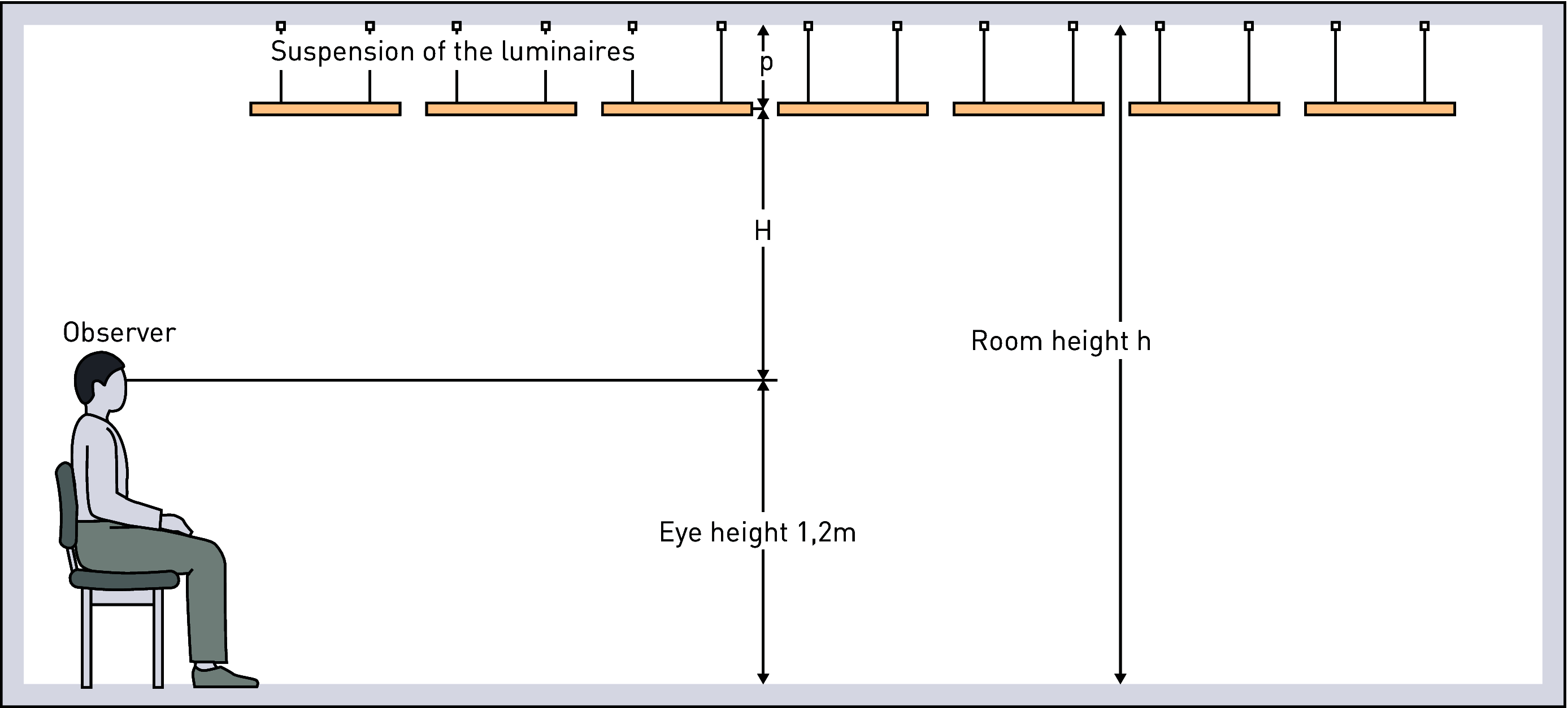
Figure 3.17: Standardised arrangement of observer and horizontal luminaire plane which is situated above H = h – p –1,2 (values in m) the observer’s eye for sitting observers, p being the suspension length of the luminaire row.
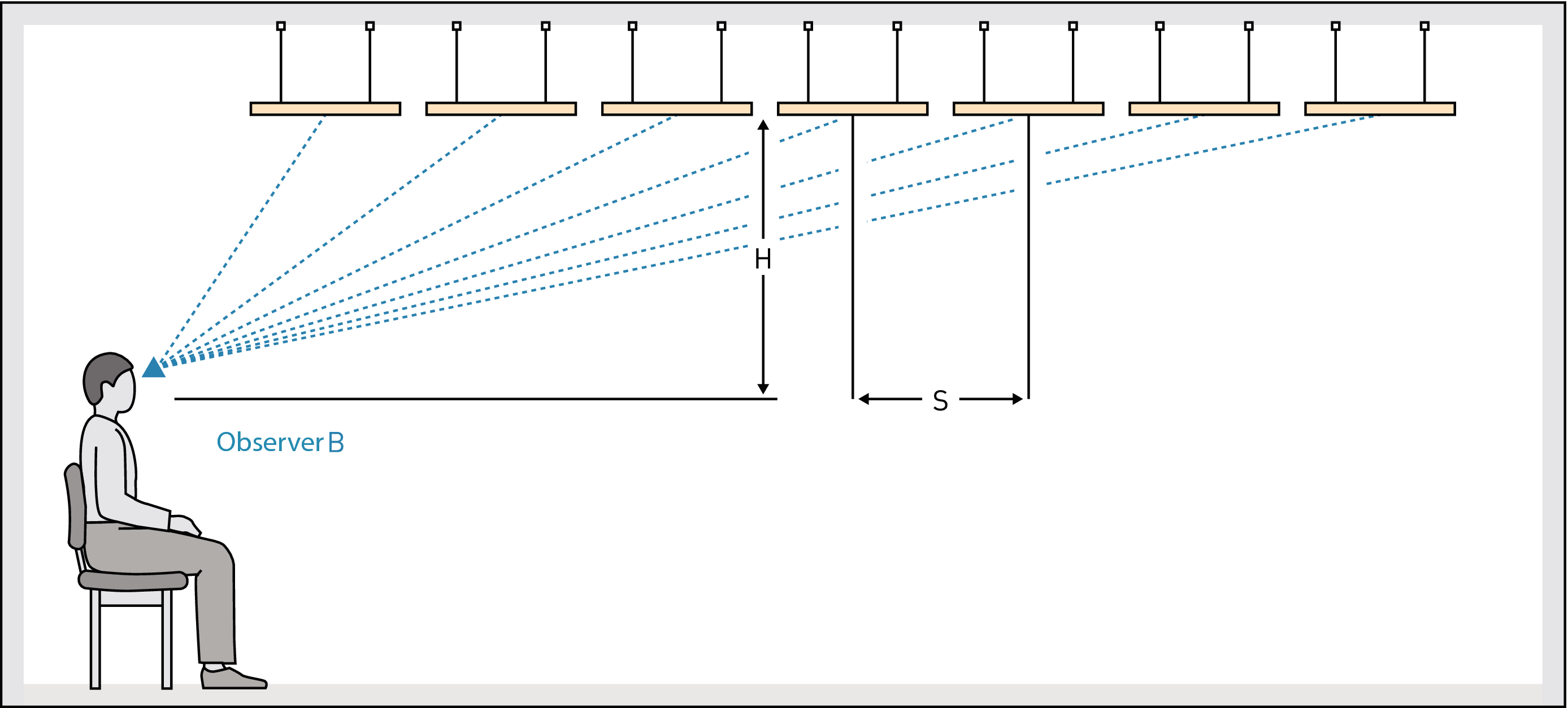
Figure 3.18: In the case of a narrow luminaire arrangement with s = 0,25 H, the UGR value is nearly independent of the observer’s position.
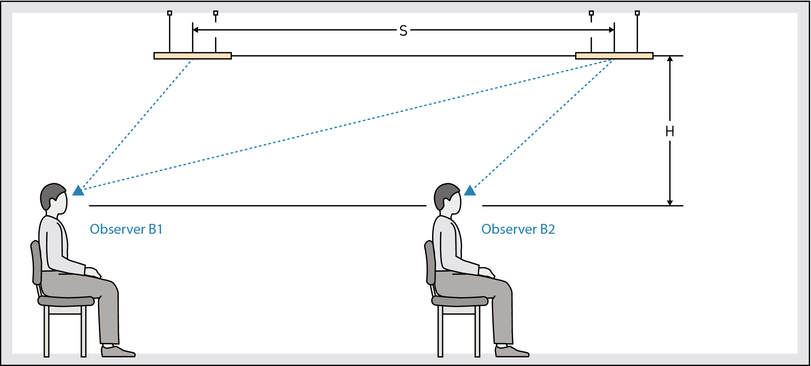
Figure 3.19: With spacious luminaire arrangements, there is a lower UGR value for observer B1 and a higher value for observer B2; however both values generally remain below the UGR value of the narrow luminaire arrangement.
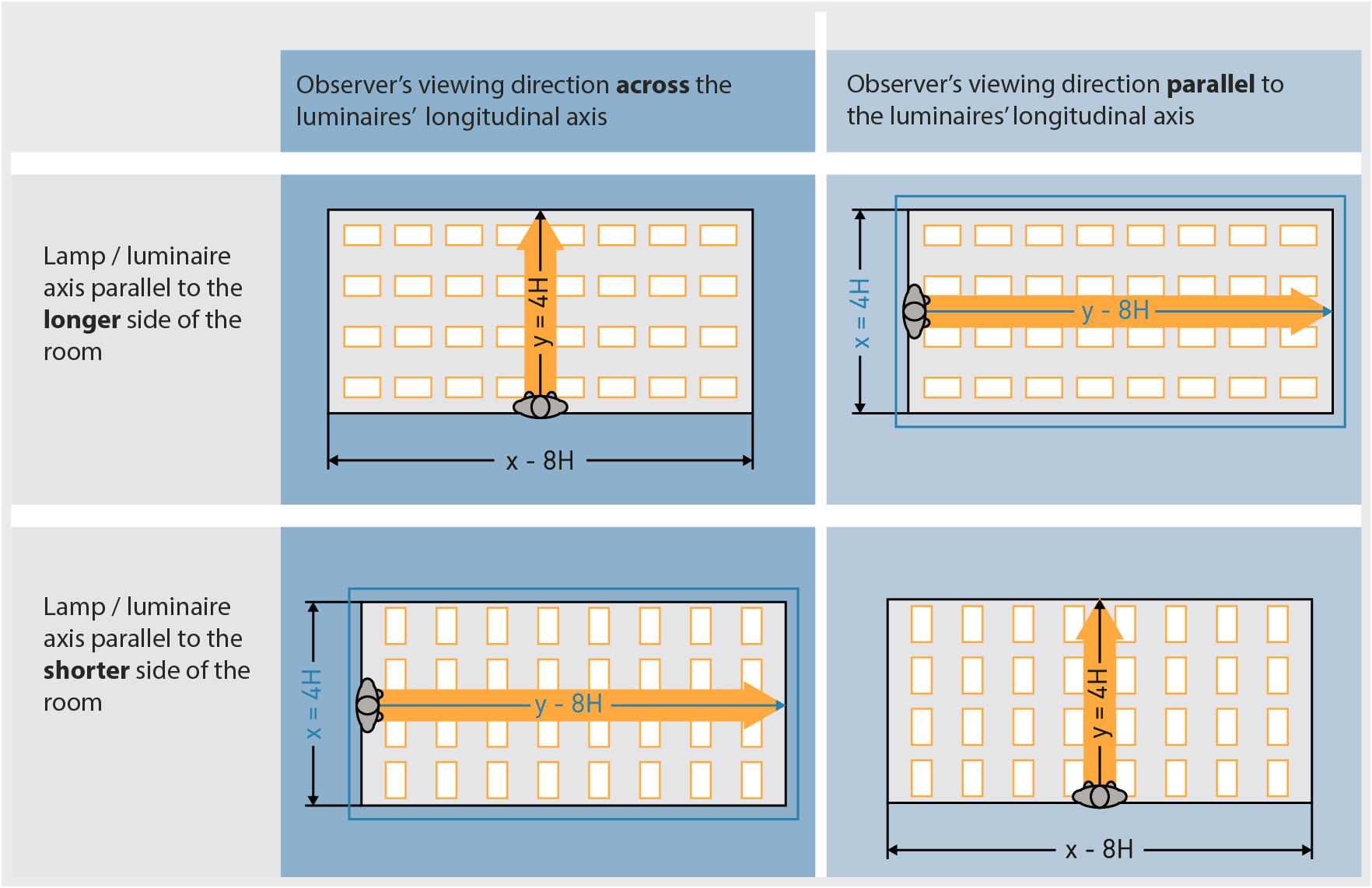
Figure 3.20: Standardised, uniform luminaire arrangements for the UGR table method. Observer's viewing direction across (left) and parallel (right) to the longitudinal lamp/luminaire axis which can be oriented parallel to the longer (above) or shorter (below) side of the room. The coordinate x is across, the coordinate y is parallel to the viewing direction. The values for x and y are example values which are revisited in blue and black in table 3.5:
Comment: For the UGR method, an observer-based coordinate system was chosen over a room-based one. The observer is always looking in the direction of y, regardless of whether this coordinate runs parallel to the longer or shorter side of the room. If the observer changes the viewing direction, their coordinates relating to the room change as well. For rotationally symmetric or quasi-rotationally symmetric luminaires such as downlights, this distinction is not applicable.
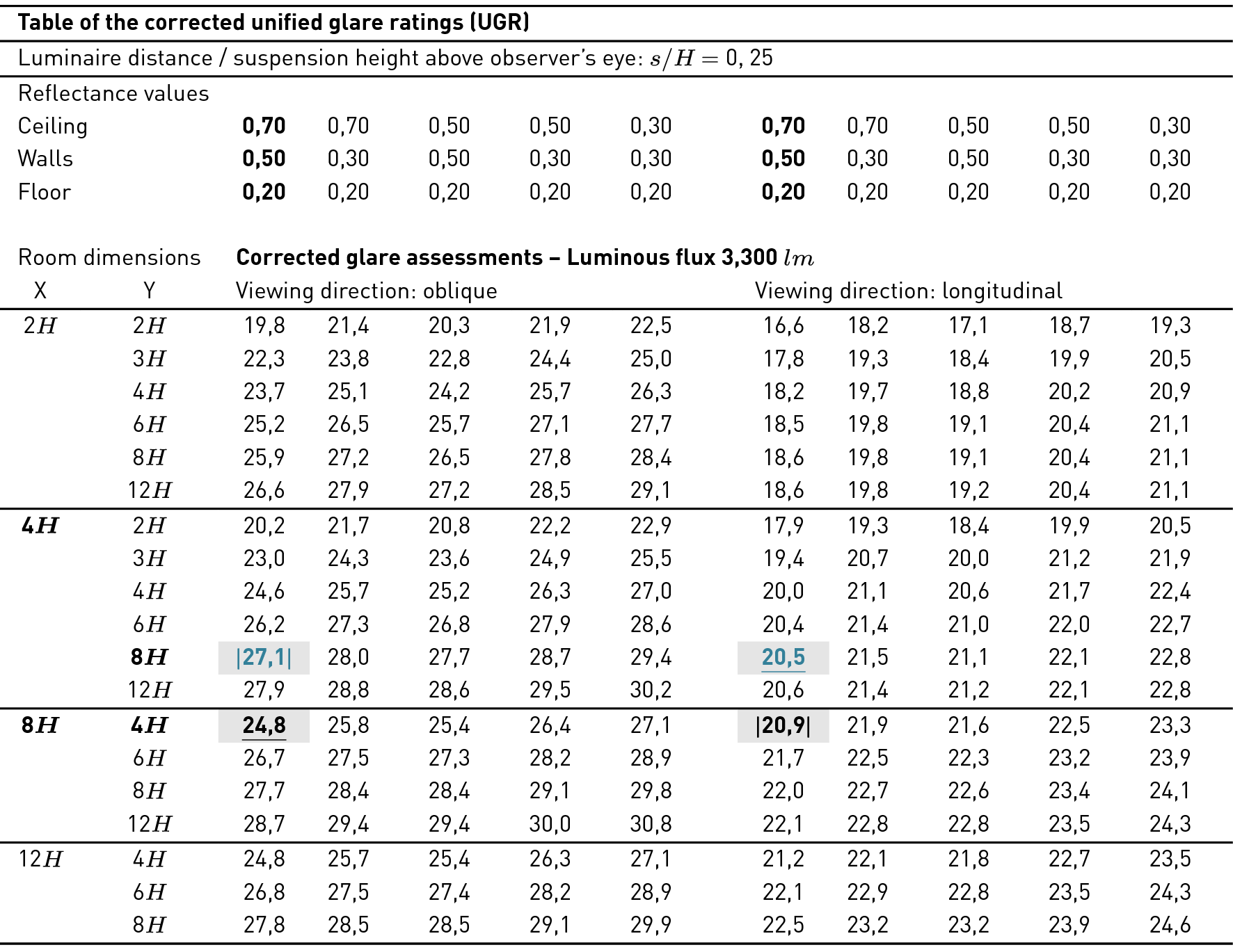
Table 3.5: Examples for a UGR table corrected to a certain lamp luminous flux for a certain luminaire for standard room dimensions x and y as a multiple of luminaire height H above the observer’s eye (definition see fig.), with standard reflectance values and for viewing directions longitudinally and crosswise to the luminaires. The values are reference values 4H, 8H for the luminaire in question. For the location of the coordinates x and y in reference to the observer, the room and the lamp/luminaire axis see fig..