Power factor

Inductors (electromagnetic coils) and capacitances (condensers) in electronic circuits impact the temporal profile of the electrical charge transfer – the current I – in the circuit when electrical voltage U is applied. Condensers are energy storage devices and feature a charge rate which ceases under constantly applied voltage once the condenser is fully charged. Inductors delay the charge transfer. When AC voltage is applied, both leads to an alternate, temporal shift in current flow size I(t) compared to the applied voltage level U(t) – a phase shift φ.

The phase shift φ can be negative or positive

with a cycle duration of 2π (radiant) of the AC voltage.

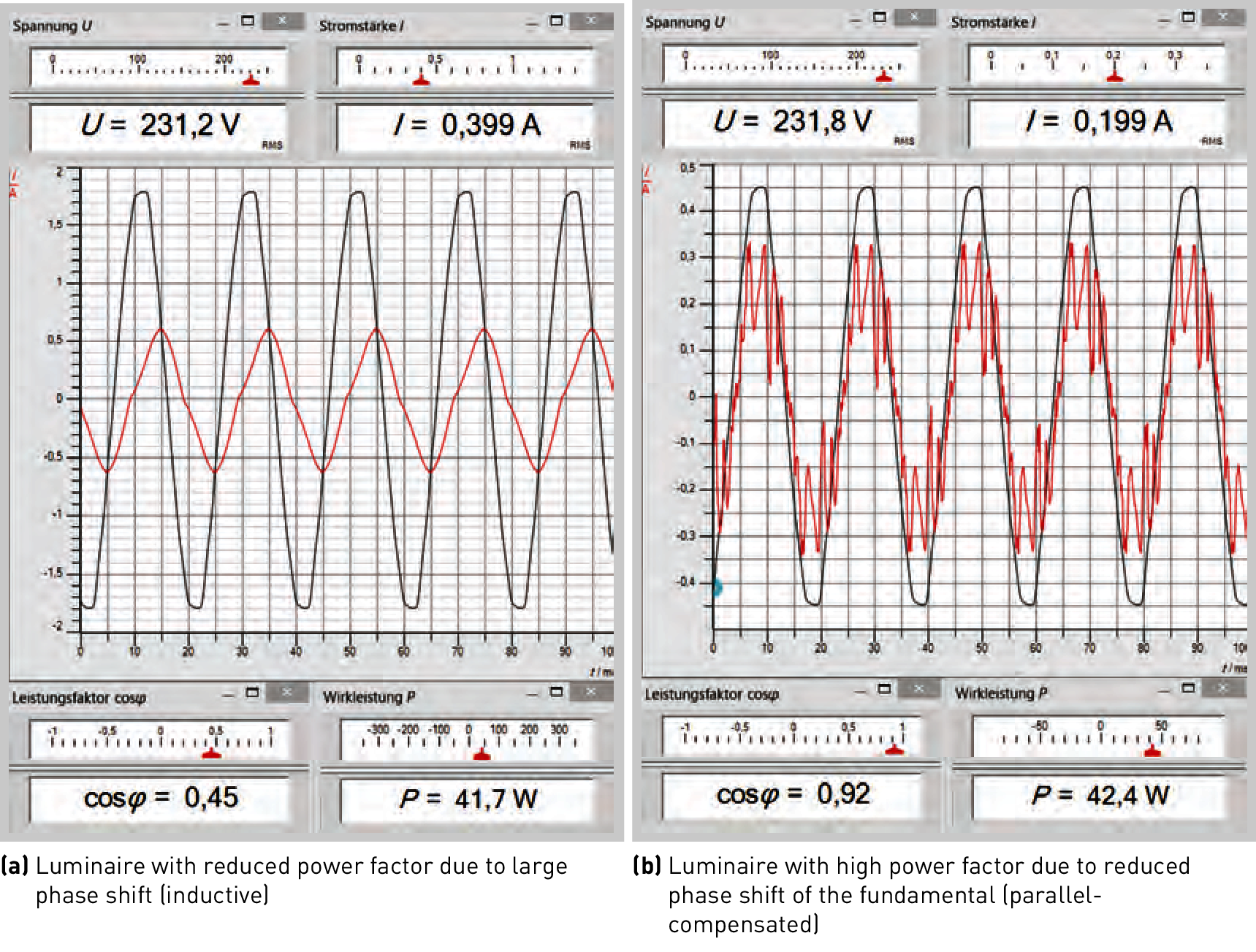
Figure 3.190: Power factor correction in a T8 luminaire (36 watts) via compensation

The power consumption of the electronic circuit at all times is

Integrating current I(t) and voltage U(t) over a cycle duration results in the so-called active power Pactive as a temporal average of P(t) and

with U and I as averages of voltage and current2 (nominal voltage and nominal current).

The factor cosφ as power factor is often expressed using the Greek letter λ.

The product of nominal current and voltage without consideration of the power factor is referred to as apparent power Papparent. The difference between apparent power and active power is referred to as reactive power Preactive.

Due to the opposite directions of phase shifts in electromagnetic coils and condensers it is possible to devise circuits in a way that causes the occurring phase shifts to cancel each other out, thereby avoiding the emergence of reactive powers.

Reactive power is always associated with reactive current Ireactive. Accordingly, active power features active current Iactive. However, apparent power is not caused by "apparent current", but by the total current Itotal flowing through the line system and thus straining the lines.

Especially when dimensioning the electrical installation (cable cross-sections and circuit breakers), the total current Itotal must be used as the basis (see also chapter ).

For purpose-designed luminaires with a power consumption in excess of 25 watts, the luminaire construction standard EN 60598 requires the apparent current portion to be a maximum of 10% of the total current caused at full capacity.

TRILUX luminaires generally feature a power factor ≥ 0.9 even if their connected load is lower than 25 watts – which is often the case due the introduction of LEDs.

Inductive luminaires (with magnetic control gear) must be compensated to comply with the power factor requirement (see chapter "Reactive power compensation").

Luminaires with dimmable electronic control gear feature a power factor significantly lower than 0.9 in dimmed or standby operation. This is permissible. When measuring power consumption in dimmed or standby operation, however, this must be factored in.

With sinusoidal voltage curves, which are ensured in the supply network, this applies for a correspondingly sinusoidal current profile. In practice, harmonic oscillation components of the current, which cannot be expressed using a phase shift relating to basic oscillation, also contribute to the power factor.