The electrical power of fluorescent lamps is converted into light and, predominantly, heat (see figure).
Lighting heat
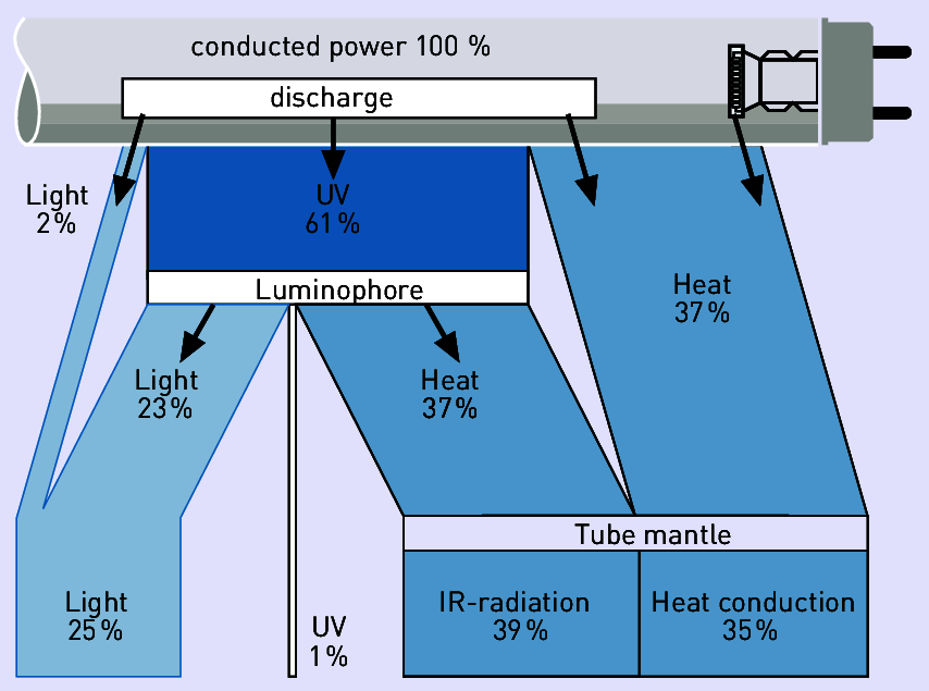
Figure 3.213: Examples for a fluorescent lamp’s energy balance
Figure depicts the heat flows of a luminaire with and without air exhausts. Explanation:
/R1 |
Heat flow emitted directly into the room |
/R2 |
Heat flow emitted through the suspended ceiling into the room |
/R3 |
Heat flow emitted into the room above through the floor in multi-storey buildings |
/z |
Heat flow emitted from the luminaire into the suspended ceiling |
/A |
Heat flow extracted with exhaust air |
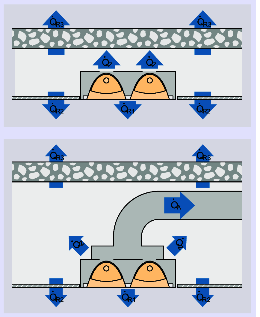
Figure 3.214: Heat flow of a luminaire without (top) and with air exhausts (bottom)
Where ventilated luminaires are operated in a low-pressure ceiling with air exhausts instead of directly connected to an air extraction channel system, it can be assumed that the heat flow removed with the exhaust air corresponds to /A + ̇/z. Since ̇QR3 from the room below also enters the room in consideration, the sum of heat flows QR1 + QR2 + QR3 is the overall effective heat emitted by lighting in the room QB, which, for luminaires without air exhausts, corresponds to the overall electrical power P of the luminaires.
The heat emitted by lighting ̇QB is determined using the following equation:

With:
P |
Electrical power of all luminaires including control gear power loss P = PL ⋅ N |
PL |
Electrical power of one luminaire including control gear power loss Values for the power of a lamp including control gear can be found in chapter “Lamp table”. These values must be multiplied with the number of lamps per luminaire to calculate the overall connected load of a luminaire. For LED luminaires, the rated output must be used (see also chapter “LED luminaire operation”). |
N |
Number of luminaires |
l1 |
Coincidence factor |
l2 |
Residual heat factor |
sB |
Storage factor |
The coincidence factor l1 accounts for the fact that in many cases at the time of maximum cooling load (e.g. due to intense sun irradiation) not all luminaires are switched on. This applies e.g. for large rooms, where a portion of the luminaires close to windows are switched off in the presence of daylight. The coincidence factor must be coordinated with the builder.
The storage factor sB accounts for the temporal delay in room air heating up due to the storage effects of the room boundary surfaces. For luminaires without air exhausts, buildings are subdivided into construction type I and II. For luminaires with air exhausts, storage factors are mostly independent from the construction type, since a large portion of luminaire heat is directly removed and thus contributes less to stored heating.
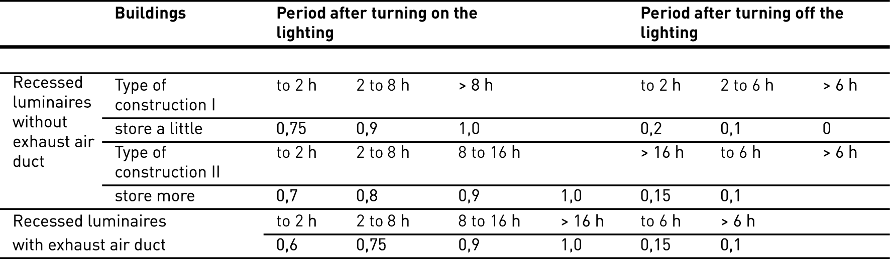
Table 3.155: Storage factors for recessed luminaires with and without air exhausts
The residual heat factor l2 specifies which portion of the luminaires’ electrical power must be factored into the cooling load determination in stationary operation. For luminaires without air exhausts, the residual heat factor l2 = , i.e. the overall connected load is cooling load. For luminaires without air exhausts, the residual heat factors depend on the air volume flow ̇V (in m3/h) as well as air exhaust system type.
In the case of air flow in low-pressure ceilings or through uninsulated exhaust ducts, a portion of the heat contained in the exhaust air is returned to the room via ceiling and floor. The residual heat factors of such systems are therefore slightly higher than those of systems with air flow in insulated exhaust ducts.
Figure contains a diagram which facilitates the determination of residual heat factors based on air volume flow of a luminaire (parameters for the straight line are luminaires for 1 or 2 lamps, 36 W or 58 W with ECG) depending on exhaust type. For example, the portion of luminaire heat burdening the cooling installation can amount to as little as 1/3 in ventilated luminaire operation within a low-pressure ceiling, depending on air volume flow (see marked example in Figure).
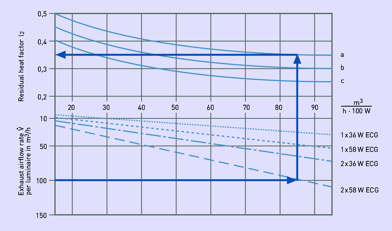
Figure 3.215: Determination of the residual heat factor
a: Air flow in low-pressure ceilings. These values apply for intermediate storeys and upper storeys. If the storey beneath the room in consideration does not contain a lighting installation, the values must be multiplied with the factor 0.9.
b: Air flow through uninsulated exhaust ducts
c: Air flow through insulated exhaust ducts
The method of luminaire calorimetry, which was used to determine heat flow with and without exhaust air on a luminaire-specific level with immense equipment effort has lost some of its significance since practice proved that usefulness and precision of the values determined using luminaire calorimeters stood in no relation to the required measurement efforts. To depict heat flow comprehensively, the entire room including its flow conditions must be considered. In special test assemblies, instead of calorimetric measurement at individual luminaires, the heat balance of entire room groups is determined for large projects. In most cases, the values depicted in figure provide sufficiently precise design data for cooling load calculations with ventilated luminaires.
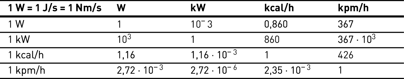
Table 3.156: Output unit conversion