Good perceptibility of illuminated bodies and surface structures essentially depends on sufficient shadow effects of the lighting.
Lighting direction, modelling
Modelling expresses the balance between diffuse and directed lighting and is an important aspect of lighting quality for practically any indoor space. The general appearance of an indoor space improves when architectural features, people and objects within it are illuminated in a way that makes shapes and surface structures clearly and comfortably recognisable. This is achieved when the light features a perceivable preferential direction which creates the unambiguous shadows important for good modelling. Lighting which is too diffuse creates a subjectively uncomfortable lack of shadows, dull work surroundings and an unattractive light ambience.
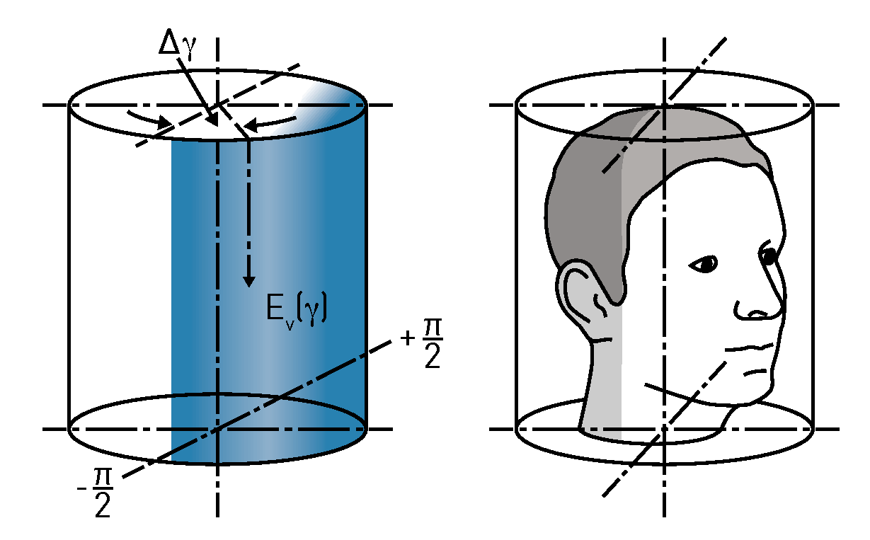
(a) To clarify semi-cylindrical illuminance as a photometric quality criterion for the perceptibility of three-dimensional visual tasks such as faces.
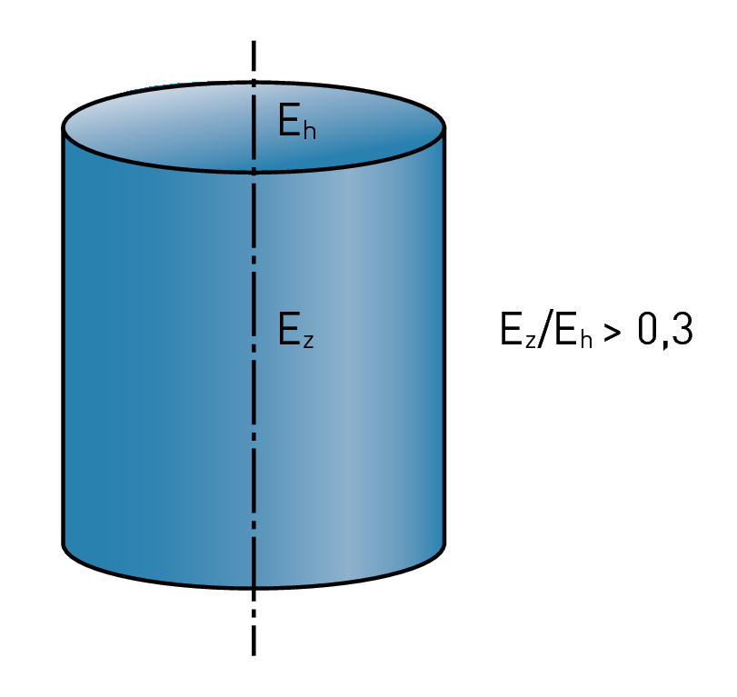
(b) The average vertical illuminance on a cylinder surface yields the cylindrical illuminance. The ratio of cylindrical and horizontal illuminance defines the shadow detail Ez/Eh at a certain point.
Figure 3.27: Semi-cylindrical and cylindrical illuminance
However, the lighting should also not be excessively directed, since this creates overly harsh shadows with sharp shadow edges. Lighting from a certain direction can emphasise details of a visual task, improve its visibility and facilitate the execution of the task for particular cases such as tooling, scoring and surface inspection. In such cases, veiling reflections and reflected glare should be considered and avoided (see chapter , "Reflected glare on horizontal visual tasks").
The lighting quality strongly depends on the perceptibility of spatial objects as well as the brightness of vertical surfaces. Comfortable visual communication depends on the perceptibility of the facial features of the persons present. A suitable photometric measurement to describe this phenomenon is the cylindrical illuminance Ez, or more precisely the semi-cylindrical illuminance Esz (see fig.).
For good perceptibility of faces, facial luminance values between 15 cd/m2 and 20 cd/m2 are considered sufficient. These luminance values correspond to an area of cylindrical illuminance between 150 lx and 200 lx. EN 12464-1 demands an average cylindrical illuminance of 50 lx at a minimum uniformity U0 of 0,10 at 1,2 m above the floor for sitting tasks and 1,6 m for standing tasks in all indoor rooms. In areas where good visual communication is particularly important, e.g. in offices, meeting rooms and classrooms, the minimum maintained cylindrical illuminance at 1,2 m or 1,6 m above the floor respectively must be 150 lx with U0 of a minimum of 0,10.
The cylindrical illuminance Ez is the arithmetic vertical illuminance Ev average at a certain point. The cylindrical illuminance according to EN 12665 is the combined luminous flux incident on the curved surface of a very small cylinder divided by the curved surface of the cylinder. Unless specified otherwise, the cylinder axis is vertical.
Pedestrians, e.g. in parking buildings and passages wish to recognise people coming toward them in time to be able to adjust their behaviour towards them. For the perceptibility of faces, semi-cylindrical illuminance Esz is also used. It is defined as the arithmetic average vertical illuminance Ev(γ) at a certain point within an angle range of the azimuth of —π/2 ≤ γ ≤ π/2 (see fig.).

Shadow detail can be rated using the ratio of cylindrical illuminance Ez and horizontal illuminance Eh. Good shadow effects are achieved when the ratio of Ez/Eh and at a height of 1,20 m above the floor is between 0,3 and 0,6. Excessive shadows can be avoided using suitable arrangements of several luminaires with a distribution which is not too narrow, as well as light-coloured walls and furniture.
Cylindrical illuminance Ez and semi-cylindrical illuminance Esz as well as shadow detail Ez/Eh can be calculated and documented in graphs using suitable software. In order to determine Ez/Eh, the matrix dots for horizontal and cylindrical illuminance must correspond.
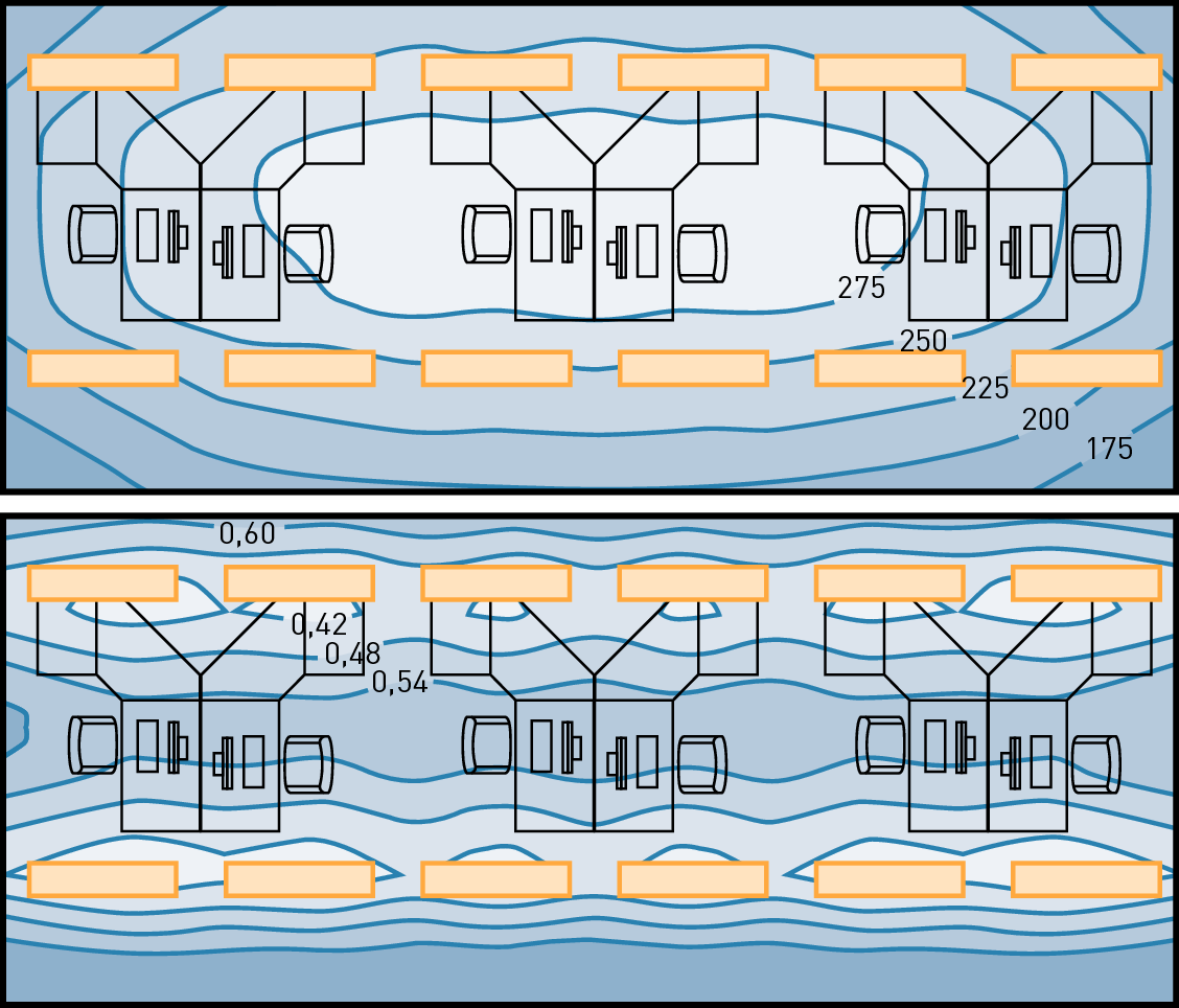
Figure 3.28: Example for documenting cylindrical illuminance Ez (above) and shadow detail Ez/Eh (below) in an office, rating plane 1,2 m above the floor.