Examples for visual task areas

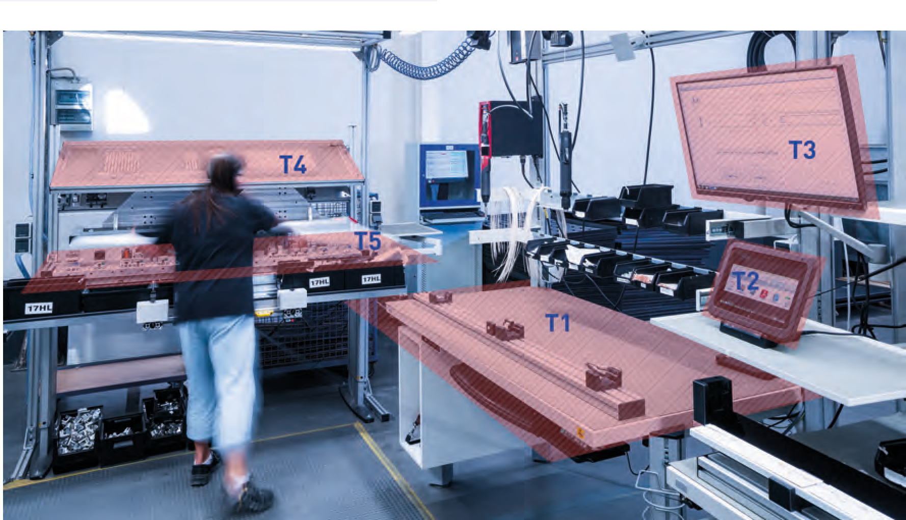
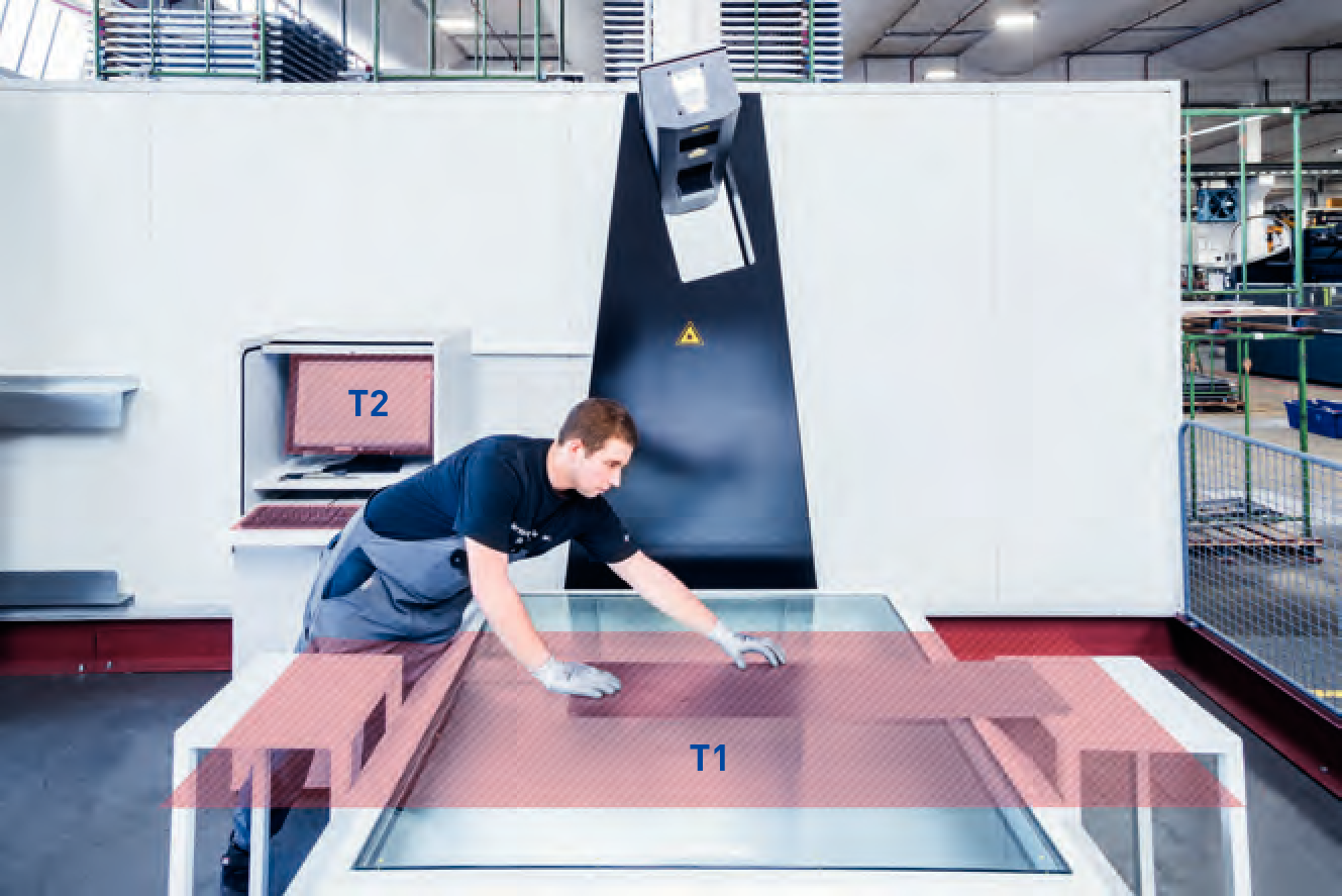
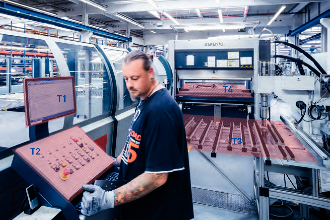
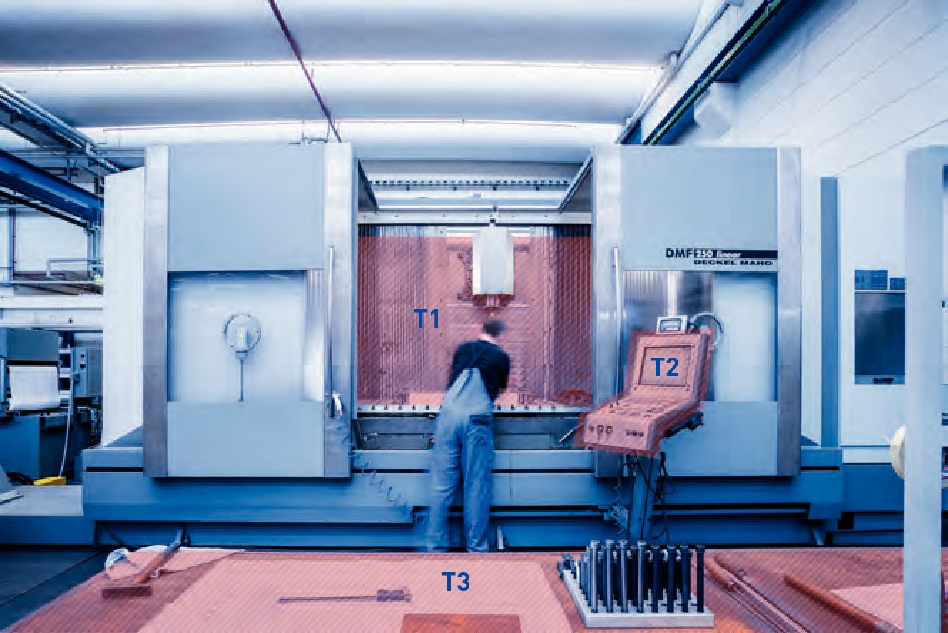
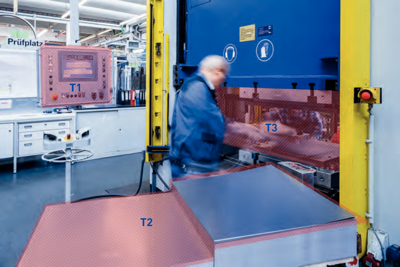
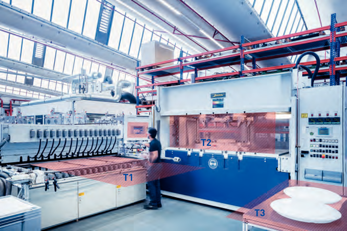
Industrial workstations can be very complex due to different visual task areas at the same workstation. This is demonstrated by the assembly workstation example. It features different visual task areas with varying positions (declination) and visual performance, therefore has varying photometric requirements.

For to the visual or working task mentioned in the figure, the corresponding illuminance and its uniformity on the partial surfaces T1 to T5 detailed in the table must be provided. The orientation of the partial surfaces is not merely horizontal, but could be vertical for screens or tilted in the placement area T4. Figure to figure show examples for industrial workstations. Visual task areas are identified as coloured partial areas.

Figure 3.83: Visual task areas at an assembly workstation.

Figure 3.84: Quality control of metal sheet via laser scanner. Aligning the component (horizontal visual task, T1) and examining dimensional accuracy on the screen (T2).

Figure 3.85: Configuration (T1) and operation (T2) of an automatic production line and subsequent stamping (T3) and creasing (T4) of the parts.

Figure 3.86: Workstation with different visual tasks: Inserting parts into a shaping machine (T1), controlling the machine (T2), measuring and finishing the part and placement of tools (T3).

Figure 3.87: Workstation with different visual tasks at a deep drawing press:
Configuration on the screen (T1), collecting metal sheets (T2) and inserting the parts with vertical and horizontal visual tasks (T3). Removal and further processing is done at another workstation at the rear of the press.

Figure 3.88: Workstation with different visual tasks:
Inserting and removing extruded PMMA plates at the radiation furnace (T1), deep drawing of parts (T2), finishing and quality control (T3).